
Configuring the Abaqus project
If you are not creating a fresh Abaqus project, but merely setting one up for connection, then not much is needed at this stage. To set up a project, you will need to know the following:
- How to check dimensions (necessary for the later configuration of the FlowVision project).
- How to create an exchange surface
- Connector type
- How to work with inp-files
Checking project dimensions
For Abaqus and FlowVision to work correctly after connection, they need to be brought to a single measurement system. For FlowVision, that system is SI, and is used for all variables and calculations. By default: lengths are dimensioned in meters, time is in seconds, pressure in Pascals, and force in Newtons.
Abaqus, however, isn’t bound to any specific measurement system. The user chooses which system to work in, and the responsibility for correctly setting parameters (dimensions) lies with them. This means that if the user has created a part in mm, then all further parameters must be specified in the dimension of mm-ton-seconds and their derivatives. For example, material density will need to be specified in tons / mm3.
There are several ways to check which unit system an Abaqus project has been created with:
- Measure the characteristic length of a part and compare it with that of the real object.
- Look in material properties and check the value for density. For example, if the it contains powers of -9, then the project has been created in mm, and the density is in tons / mm3.
It follows that if the projects have been created using different systems of measurement, then for a joint calculation to work correctly, they must be brought to a single system. This can be done in one of two ways:
- Set all FlowVision values matching the Abaqus system of measurement. This is quite labour intensive - you can easily make a mistake, manually translating all values from one measurement system to another. We do not recommend using this approach.
- Use scaling factors for geometry, loads, and temperatures.
Creating an exchange surface
To set up the connection between the ABQ and FV projects, you need to select a surface within Abaqus to receive load data from FV and deformation data from ABQ. The exchange of these two sets of data will happen along this surface.
To create an exchange surface, you need to be able to work with geometry in Abaqus. At the very least, you need to be able to create surfaces by selecting parts of the geometry. The Create option in the Assembly module in the Surfaces section will help you here:
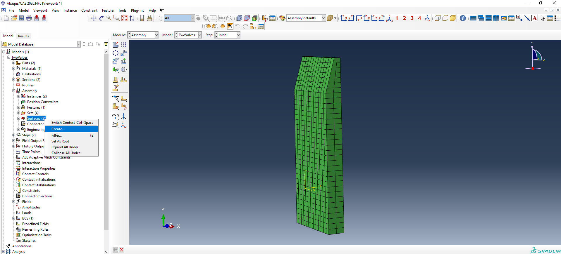
When selecting a surface, you should turn your attention to where and how it is being created. There is a risk that the surface will be created on the inside of a part, on part of a part, or on the inside of an element. This is especially likely when constructing from Shell elements. If you are using them, then when creating the surface, select the correct side of the shell using the Choose a side for the shell or internal faces option. For most FSI projects it is the outer surface that is used to transfer loads. Also, keep in mind that the exchange surface must be closed. More about requirements for exchange surfaces here.
Connector type
Currently, one of two types of connectors can be used to connect to Abaqus:
- Abaqus Direct Coupling
- Abaqus CSE.
The first (Abaqus Direct Coupling) is an outdated connector type that mainly works with older versions of Abaqus (up to and including Abaqus 2016).
The second (Abaqus CSE) is a newer connector that facilitates interaction with later versions of Abaqus (Abaqus CSE - v2017 onwards).
Working with inp files
An inp file is an Abaqus file that contains a description of the entire project in text form. It can be opened with regular notepad or the more advanced Notepad ++ (more convenient).
To work with FSI calculations, it is imperative to learn how to work with inp files. At early stages, you won't need to modify this file much for simple calculations. For example, in one tutorial project, you just need to add co-simulation lines to the end of the file. But for complex projects, more significant changes may be required, for example, manually adding exchange surfaces, or adding / removing boundary or initial conditions.
The co-simulation lines contain the following information:
- The type of joint calculation - whether the connection uses Direct Coupling or CSE connector.
- The name of the exchange surface (must be preceded by ASSEMBLY_).
- The transmitted variables: U = displacements, COORD = coordinates (for Abaqus), PRES = pressure, CF = concentrated force (for FlowVision).
- Settings for joint calculation, if it is a Direct Coupling connection (e.g. time incrementation = subcycle, time marks = yes)
For more information on co-simulation parameters for various connectors, see the Abaqus documentation.