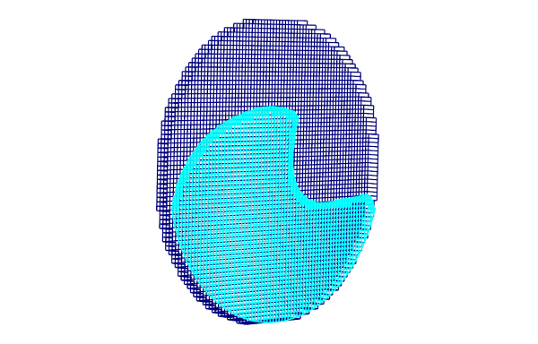
Advanced users of FlowVision are certainly familiar with the trick of using a remote non-computational subdomain for 2D simulations that utilise grid adaptation. This non-obvious method is used to disable mesh adaptation along one coordinate direction, thus making sure there will be only one cell across the width of the computational space. Despite being complicated, the trick works and helps to minimize computational mesh in 2D simulation.
In the new release of FlowVision, the 2D-simulation option is built into the program interface. Now you can create a project with 2D adaptation in just one click. Furthermore, the creation of projects with a 2D-sector condition has become easier.
You can try it! In this article we'll be talking about why it's so important to first perform a 2D calculation instead of directly jumping into a 3D one.
- Typical cases using 2D condition
- "2D direction" option is the new way for setting 2D adaptation
- Frequently asked questions about the new 2D adaptation method
- A brief summary
Typical cases using 2D condition
At first glance it may seem that 2D calculation is disconnected from the laws of physics of 3d space, in which we and all the objects surrounding us exist. But that`s not actually true, because 2D calculation just disables the distribution of disturbancesalong one of the coordinate directions. It is, of course, a distortion of the full picture of results, however it`s more than acceptable for getting a quick estimation. For this reason, it is recommended that work on a complicated project should begin with a 2D calculation.
You can't even imagine how much you can make your life easier if you approach complex 3D problems by first modelling in a two-dimensional setting!
Moreover, practically any task can be simplified at the first stages and presented in 2D. There are many examples of various 2D modelling approaches in the FlowVision tutorials. However, should you encounter technical difficulties in simplifying your task to 2D, contact the FlowVision tech support team (support@flowvisioncfd.com), we would be happy to help! In the meantime, we will tell you three reasons why 2D calculation should be used in the modelling approach to any problem.
1. Solving verification problems
Verification has two goals:
- to evaluate the capabilities of a CFD program in solving a particular problem
- to find the best solver settings for your simulation
Verification data is usually based either on a real experiment (from which we get flow images and parameter values for certain points in space) or on a computational experiment (in which users just like you perform 2D calculations). Therefore, to save time and computational resources, the verification stage can be successfully completed on a "cheap" 2D project.
2. Performing grid and time convergence studies
Here we will talk about an extremely important stage of the calculation process (the credibility of future results depends on it!) and also the most resource-intensive. We have already written how to properly do a convergence investigation. But in the shorter way, to find out the right grid cell size and time step value you have to about 6-10 calculation in average. And much easier to do it in the 2d analogy of the real task. You will not only faster find the optimal grid and step (even taking into account that 1 - 2 calculations will holding with an excessively fine grid and step), but you will also be able to quickly assess the impact of local grid adaptation.
3. MODELLING EFFECTIVELY TWO-DIMENSIONAL PROCESSES
As an example, when modelling flow of a very viscous fluid, flow in the transverse direction is negligible due to high inertia of the viscous medium, and can be ignored. Another example is the modelling of cross-flow over heavily elongated bodies. At any cross-section along such bodies the flow will be the same, so we can avoid unnecessarily complicating the formulation and instead model just one cross-section in 2D.
A NEW WAY TO DEFINE TWO-DIMENSIONALITY - " 2D DIRECTION"
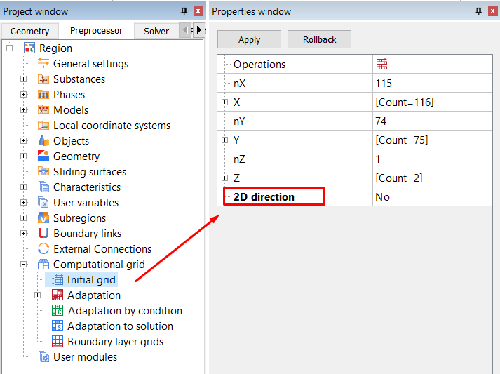
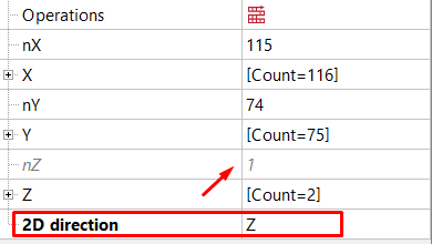
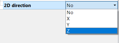
Starting from version 3.12.02 two-dimensionality can be set by enabling the "2D direction" option, located in the properties window of the Initial grid tree element.
If "2D direction" is disabled (2D direction = No), the project is considered as a 3D problem. In this case, the number of cells in each direction is set manually in their respective fields. If, additionally, you apply grid adaptation, each cell is divided into two parts in each coordinate direction, for every level of adaptation. So if you have set for there to be only one cell in some dimension, you have indeed created a 2D statement. However, after the adaptation is applied the two- dimensionality will be lost, and the overall number of cells will significantly increase. But we would like to avoid this, therefore…
When you specify a 2D direction (X, Y, or Z)*, this automatcally sets a thickness of one cell in that dimension. And this will remain the case throughout the calculation regardless of any grid adaptations. It should be noted, that when using the "2D direction" option, you do not need to change the criterion for small cells from absolute to relative, as was required in previous versions.
* - you can set only one 2D direction
SPECIFICS WHEN SETTING TWO-DIMENSIONALITY IN A PROJECT
Let's consider the specifics of setting two-dimensionality for two types of geometry: flat and sector.
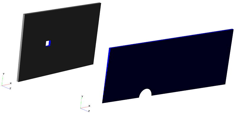 Examples of flat (flow around a cube) and sector (flow around a sphere) arrangements with two-dimensionality in the Z direction
Flat 2D arrangement
- BC types on faces perpendicular to the 2D direction: symmetry, the wall or the connected.
- The model size along the 2D direction: there are no restrictions. The cell thickness across the geometric model can be any size relative to the cell dimensions in other directions: both, narrow and, conversely, very elongated.
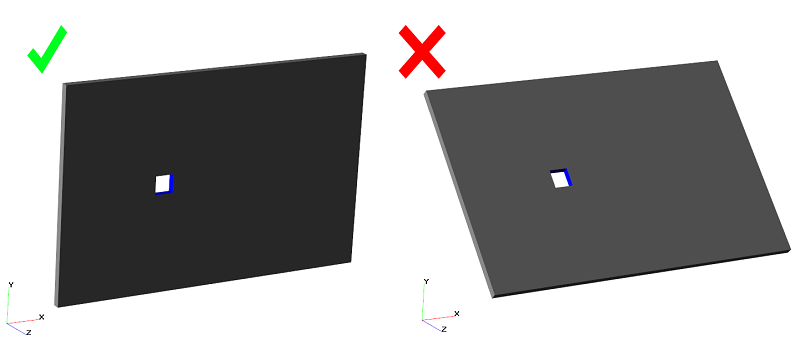
- The model position in a space: the normal to each facet of the geometry must be either parallel or perpendicular to the specified 2D direction. This means that the narrowest face (the one ususally set to be one cell thick) must be strictly parallel to the specified 2d direction.
By using the "2D direction" option, the criterion for small cells remains absolute by default
The relative criterion should be used only for solving icing problems ("Ice" phase limiters > Small cells = Relative). Since the ice phase is formed gradually and with the help of small cells, in order to prevent them from merging into one, it is necessary to use the relative criterion for small cells, in all other cases - it should be absolute.
sector 2D arrangement
The two-dimensional sector statement is modeled only with enabling the "2D direction" option.
- BC types on faces perpendicular to the 2D direction: symmetry, or connected.
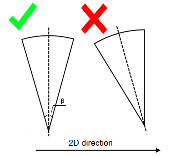
- The model size along the 2D direction: there is a limit on the value for the sector angle (β): β ⩽ 10 deg.
- The model position in a space: the sector symmetry axis must be strictly perpendicular to the 2D direction, as shown in the image below.
By modeling a 2D sector arrangement, specify the "2D direction" and the absolute criterion for the small cells
- When can a two-dimensional project be simulated without enabling the "2D direction" option?
- How can two-dimensional projects from earlier software versions be adapted to the new one?
- What should be done if FlowVision blocks setting the "2D direction" for the geometry?
TWO-DIMENSIONAL PROJECT with disabled "2D DIRECTION"
In some cases, when creating a two-dimensional calculation, it's possible to not use the "2D direction" option.
case № 1 - TWO-DIMENSIONAL PROJECT without adaptation
The 2D direction was created as a replacement for an inconvenient technique that helps to save the two-dimensional grid in the adapting prosses. If you don't intend to use grid adaptation, then you can leave "2D direction" disabled. However, if at some stage of the simulation, there arises a need for adaptation and you go to enable "2D direction", then you will only be able to start simulation from the very begining. Unfortunately, FlowVision is unable to continue the calculation from where it left off, as the initial grid settings will have changed.
case № 2 - TWO-DIMENSIONAL PROJECT from a previous FlowVision version
Flat and sector two-dimensional projects from previous versions work well even in FlowVision 3.12.02. To continue running them, you do not need to set the 2D direction or make any changes to the project. You can still use the old-fashioned method with a non-calculated remote subregion, or set for there to be one calculated cell along a chosen direction. But it would be extremely welcome if you adapt the old two-dimensional project to use the new method. The next point is dedicated to this.
ADAPTING A 2D PROJECT FROM EARLIER VERSIONS OF FLOWVISION
WHY DO WE RECOMMEND REPLACING THE method WITH A REMOTE SUBregion WITH enabling "2D DIRECTION"?
- It becomes slightly easier for the solver to interpret two-dimensional projects set up using "2D direction". "2D direction" is now a part of the FlowVision program code, rather than a user-created technique.
- Use of the absolute criterion for small cells allows us to obtain a more stable solution, especially for problems involving VOF. In any unclear situation, it is better to use the absolute criterion, rather than the relative one.
- An aesthetic, but no less important factor: a project without a remote subregion looks much neater.
To adapt a two-dimensional project from earlier versions and calculate it in FlowVision 3.12.02, you only need to perform three steps:
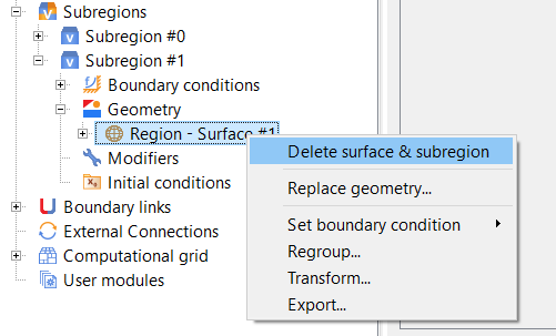
Step 1: delete the non-computational subregion
Step 2: specify the "2D direction" in the initial grid properties window
Step 3: set absolute criterion for small cells in phase limiters
WAYS TO SOLVE PROBLEMS encountered when trying to SET THE "2D DIRECTION"
 If this warning appears when setting the 2D direction for two-dimensional calculation, then:
- check that the geometry satisfies the FlowVision two-dimensional criteria.
- rotate a geometric model by transforming the geometry (Region > Transform Geometry > Rotation)
- keep in mind that the program provides restrictions for sector arrangement: for value of sector angle (β ⩽ 10 град) and for the BC, specified on the faces intersecting the 2D direction (the symmetry and the connected). - raise the import precision CAD geometric models. It is possible that the geometry has a very rough grid representation, and not all facets satisfy the criteria for two-dimensionality.
- report your issue to technical support (support@flowvisioncfd.com). Please, don't forget to attach the "problem" geometric model!
BRIEF SUMMARY OF THE ARTICLE
- A two-dimensional formulation simplifies the debugging of a project at the very beginning of modelling a complex process. It is more rational to perform the tasks of verification and solution convergence studies in a 2D formulation. The modelling of some processes doesn't require a 3D simulation at all.
- In FlowVision 3.12.02, a new method for setting two-dimensionality has replaced the method with a remote non-calculated subregion. A non-calculated remote subregion was an intermediary technique developed by our engineers. Now there exists a software solution - the "2D direction" option.
- When using the 2D direction, you should always use the absolute criterion for small cells, which is set by default (Limiters > Phase Limiters > Small Cells = Absolute).
- For flat and sector 2D arrangements, the technique with a non-calculated subregion continues to work. However, we highly recommend that you adapt 2D projects from previous versions to use the "2D direction". This will allow you to get a more stable solution (since the absolute small cells criterion will be used, and not relative, as before), and the overall project will look neater.
