The future belongs to FSI simulations! It's no secret that co-simulation, CFD + FE, is becoming more and more in demand. Such modeling, covering both body deformations and hydro-gas dynamics, allows to obtain more accurate and reliable results in the fields of aircraft engineering, automotive, biomechanics and many others.
In the case of FlowVision, this technology is implemented as FlowVision co-simulation with various FE-codes: Abaqus, APM, Fidesys. At every exchange step, the FE-code transfers a deformed geometric model, and FlowVision models the flow process for it. The geometric surface over which data is exchanged is called the exchange surface, and it is one of the most important elements in FSI interaction.
But what if the geometric model has a number of errors or certain defects? There are several approaches to solving such problems.
The first approach is - to fix the geometric model according to FlowVision requirements using methods described in the Documentation. This is a rather resource-intensive process, which sometimes involves a significant modification of the model geometry and may take a lot of time. And in some cases, it is simply impossible to do this without losing the task specifics. Therefore, there is a second approach – to use surface mapping.
- Why may problems appear, when you are working with the exchange surface?
- What is mapping and why is it needed?
- Advantages of mapping
- How to work with mapping?
- What parameters in the mapper setup may be changed?
Why may problems appear, when you are working with the exchange surface?
The main reason is simple: different software systems have different requirements for geometric models. FlowVision is able to work with different formats of geometric models, but there are some limitations: it is impossible to use geometric models with self–intersections, overlaps and, most importantly, open surfaces.
What is mapping and why is it needed?
To avoid troubles when working with co-simulation, you can use a special FlowVision option – mapping. Let's figure out what it is.
The mapping option maps one surface to another by searching correspondences between solid angles of elements. The figure below shows that when data is exchanged directly, it is transferred through a grid surface (figure on the left) obtained from a FE-code, and when data is exchanged with mapping, it is transferred through a special surface (figure on the right) based on the FE-geometry. In other words, the mapping surface is an additional surface, an interlayer, through which loads from FlowVision are transferred to Abaqus or another Finite Element code.

In Figure: fji – loads transferred from the i-th cell to the j-th face, fjm – loads transferred from the m-th cell to the j-th face, Fj – total load to the j-th face.
Advantages of mapping
Mapping can help to avoid troubles with the FE-model. But for correct use, mapping surface should meet basic requirements: to be closed and not to have self-intersections. If it doesn't meet the basic requirements, it needs to be fixed. This may be done with any CAD program.
It's worth warning right away: FlowVision doesn't know how to fix your geometry, you have to do this by yourself
There are several advantages, that should be highlighted for mapping:
A coarse mesh can be used in the FE model, while a more precise mesh is needed in the CFD software, where surface quality is important. In this case, the number of nodes on one surface will not correspond to the number of nodes on the other surface. For transferred data – loads or deformations, linear interpolation of values to the nodes of the mesh will take place. Let's consider an example of using a mapping surface in the task of aeroelasticity of an aircraft wing in a transonic flow: for FSI-simulation, mapping surface with a good resolution has been prepared using FE software (in the figure it is the model on the right). In turn, the model itself involved in the FE-simulation doesn't require such a qualitative representation (in the figure, the model on the left). Using this approach allows:
- Speed up the FE-simulation due to the "rough" FE-model;
- Increase the accuracy of CFD-simulation in FlowVision due to surface with highly refined grid (mapping surface).

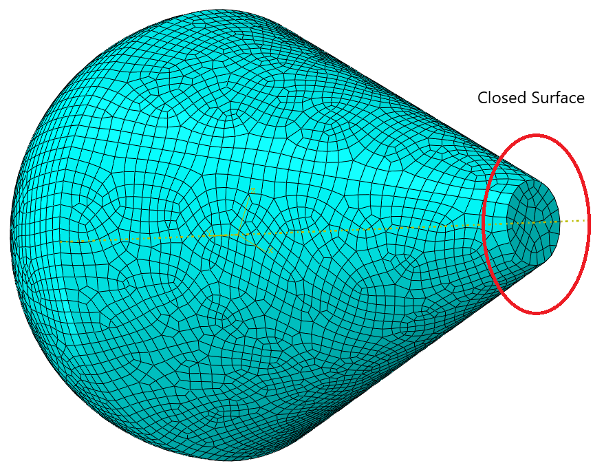
If the FE-model is a surface with open elements, then such elements will be interpolated taking into account the boundary nodes and the location of nodes on the mapping surface. Consider the example below – modeling a balloon surface. For FE software, such a task is not a big problem - the surface can be meshed with ordinary shell elements, but it will not work for FlowVision, since this surface is open. The solution is quite simple – for the FSI simulation, as the exchange surface used in FlowVision, you can set exactly the same surface with one difference – it will be "sewn" at the bottom. The FE-simulation will use its own initial surface (unclosed), while the FlowVision simulation will use a closed surface, data from which is transferred to the FE surface.

Suitable surface for FlowVision:
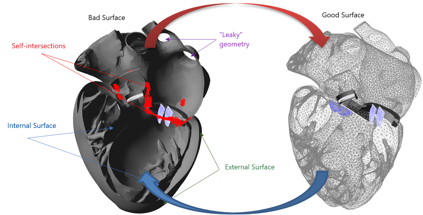
The last and the most important: if FE-mesh has defects (self-interactions, overlaps and so on), then the mapping surface that does not contain these defects can be used. An excellent example illustrating this feature is the FSI-simulation of the heart, where the total surface of the whole heart is used. One "ideal" closed surface without self-intersections has been created for the FlowVision project, and the initial surface with intersections is modeled in the FE software.
Useful addition
Only one boundary condition (BC) can be specified on the exchange surface in case when mapping surface is not used (Mapping -> Enabled = No). This limitation is explained by the fact that data exchange occurs through a surface obtained directly from the FE-code. If the Mapping option is enabled, then different BC can be assigned to one FlowVision surface, as well as supergroups can be built (very convenient if you need to get data on variables directly on the deformable object or part of the object).
How to work with mapping?
In order to use Mapping, you will need:
- A FlowVision project
- A project created in a FE software, configured for FSI connection (with added co-simulation lines)
- A geometric model similar to the FE project model, but satisfying the FlowVision requirements, prepared in advance.
If the geometry model is "bad", it should be transformed before working with it using FlowVision. By importing geometry into any CAD system, eliminating all self-intersections and stitching the borders together, we get a CFD surface that can be used in FlowVision. Switching on Mapping for FSI simulation, this geometric model can be used in calculation:
- In the PPP tab Objects create an Imported object based on the prepared geometric model. This will be your mapping surface.
- Create modifier Moving body in the Imported object tab.
- Create any External Connection.
- In the Properties window choose Moving body.
- Choose Mapping -> Enabled = Yes.
As for now, the surface from FE-code is connected with the mapping surface. Data from the mapping surface will be interpolated to the FE-grid.
FSI-project with mapping surface
Let's consider FSI-simulation case when complex geometry is used, model of human's heart, for example. In FE-project, the geometric model is created as assembly: the ventricles and atria are separate objects, and the assembly elements are interconnected by various constraints and contacts. But from the FlowVision point of view, such a surface is unclosed and has defects (self-intersections and overlaps), which are categorically unacceptable.
Mapping parameters
After creation an External connection for each of the automatically created exchange surfaces, you can select mapping settings in the properties window. FlowVision 3.13.03 mapping parameters window looks like:

Enabled: Yes/No.
The Mapping option allows to enable mapping or (in case of "No") not to use it. By default, Enabled = No.
This parameter specifies whether the initial or deformed surface of a FE-object will be used to construct a mapping surface (mapper). With zero exchange, the
FE-code sends interchange package with two surfaces to FlowVision: the initial one and the current one, deformed under the action of loads. That is, if a pre-calculation in the FE software take place or the calculation starts not from the scratch, it is necessary to use deformed geometry. In other cases, you can use the parameter Surface: Initial.
The choice of the surface type is very important, if the FSI-simulation starts with already deformed geometry
Mapping surface is built at the beginning of the simulation. If the geometric model of the moving body for which the mapper was built does not correspond to it, then the mapper is rebuilt. In other words, if the surface that came from the FE-code on the first exchange differs from the surface in FlowVision, and the option Rebuild mapper = Yes is enabled - the mapper will be rebuilt. However, it is a rare case, so the recommended value is No.
Summary
- Mapping - option for FSI-simulations, which allows using an intermediate – mapping – surface (rather than a direct geometric model coming from the FE-code) for data exchange between CFD and FE-softwares.
- Enabling this option has advantages:
- The FE geometry quality doesn't affect the CFD simulation. CFD has its own surface, with its own mesh quality.
- The FE surface may be unclosed. Use a closed-surface mapper in accordance with all the requirements for geometric models in FlowVision.
- Defects of the FE-mesh do not affect the CFD calculation surface, since the mapping surface should be prepared in such a way, that it doesn't contain defects.
- Two key parameters are used, when configuring mapping in FV:
- Surface: Initial or Deformed. The choice of the surface type is very important, if FSI simulation starts already on a pre-deformed surface after restart in FE-code.
- Rebuild the mapper: Yes or No. If the surface of the moving body, that came from the FE-code on the first exchange, differs from the surface in FlowVision, the mapper will be rebuilt when the option is enabled Rebuild the mapper = Yes. But this situation is rather rare, so it is recommended to use Rebuild the mapper = No.
Read more about mapping in the documentation. And if you need help with mapping, e-mail us at support@flowvisioncfd.com.