Now it's easier to simulate sea waves in FlowVision!
You may set complex boundary conditions for the formation of natural gravitational waves using the formula editor. But these formulas are quite complex. Therefore, we used the computational engineering platform API and connected this module to FlowVision, so it became convinient to create user boundary conditions which generate waves.
In this article we will tell you:
- what is a wave generator and where to find it;
- how to connect it to the FlowVision project;
- what are the features of the wave generator module;
- what parameters should be set in the properties window;
- how to create a project with waves;
- what important settings should be taken into account.
Also we will show results of wave simulation in FlowVision.
WHAT IS API of computational ENGINEERING PLATFORM
The API allows users to create their own modules that can be connected to FlowVision to expand the CFD package capabilities or to simplify some routine operations.
Currently, the API allows to create libraries for:
- calculation of local variables;
- creation of unique user boundary conditions;
-
to including models of devices, which are not simulated in FlowVision. For example, you can define mass flow and pressure of a pump and put it in API library. Then in another project API library will set only this values at the inlet and outlet of the volume replacing the pump .
WHAT IS the WAVE GENERATOR?
The wave generator is a plug-in module for FlowVision that has been created by our developers using the engineering computational platform API. Initially this module was created for solving shipbuilding problems. Wave generator is based on Stokes' wave theory. Now, there is no need to write complex formulas on the inlet BC to set the wave formation, instead of this just connect a special module to the FlowVision project.
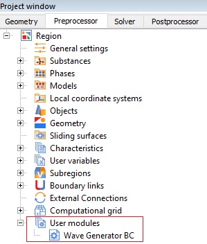
HOW TO CONNECT WAVE GENERATOR TO the FlowVision PROJECT
To connect the module just add the WaveGeneratorBC.fvdll library to the User modules folder in the project tree. You can find WaveGeneratorBC.fvdll in the installation directory: C:\Program Files\FlowVision-3.12.01\SDK\examples.
The wave generator is compatible with FlowVision version 3.12.01 and higher.
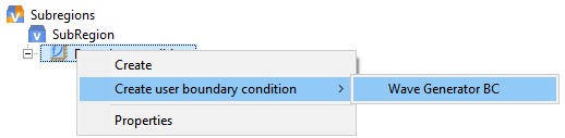
After connection, it becomes possible to create user boundary condition for inlet - "Wave Generator BC".
CAPABILITIES OF THE WAVE GENERATOR
You can use wave Generator to simulate waves:
- with different direction
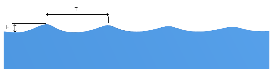
- with different oscillation period (T) and height (H)
- with different relative velocity of the moving object
PARAMETERS IN THE PROPERTIES WINDOW
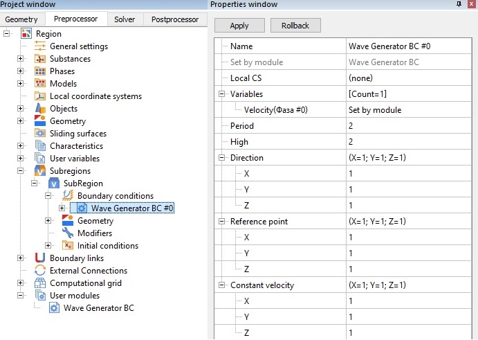
To set a wave in the FlowVison project, specify the following parameters in the properties window of the "Wave Generator BC":
- Oscillation period – the period of time during which any point of the wave front makes a complete oscillation (2?);
- Wave height – distance equal to the oscillation amplitude;
- Direction – vector of wave propagation in computational space;
- Reference point – coordinates of a point lying on the plane of the zero level of the wave;
- Constant velocity – the velocity of propagation of the wave front.
HOW TO CREATE A PROJECT WITH WAVES
We will show how to create waves in FlowVision on the example Boat the tutorial. To do this follow the steps below:
- Open the client part of the project.
- Connect the Wave Generator module.
- Create a user boundary condition - the Wave Generator BC.
- Specify the wave parameters in the Wave Generator BC properties window.
Wave Generator BC properties window
- Assign the "Region - Surface #0" geometry as the Wave Generator BC.
- Run the project and enjoy the picture of wave formation. Be careful and don't sink the boat: there may be people on it.
KEY SETTINGs
If you are going to add waves to your project, don't forget about these important settings.
GENERAL SETTING
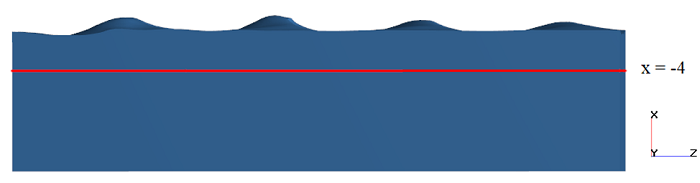
- It`s important for VOF tasks to set hydrostatic pressure (phydr) in General settings. To do this, specify the values of the g-Point (it should be located on the reference line of the wave) and the g-Layer.
- Also, you should set the gravity vector (g = 9.8 m/s2).
BOUNDARY CONDITIONS
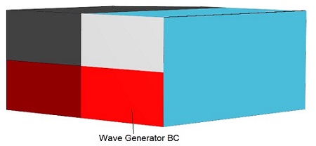
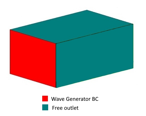
The types of boundary conditions depend on the specifics of your task. We will tell you about the possible options for choosing boundary condition for waves simulation in an infinite water space. We recommend to use the Free output on the top face and the Symmetry on the bottom face of computational domain.
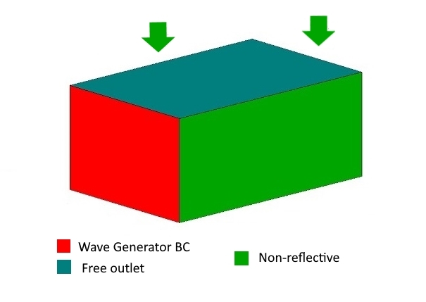
You may set are the Free Outlet BC or the Non-reflecting BC opposite to the "Wave Generator BC".
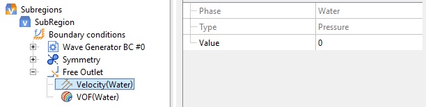
FREE OUTLET
Free outlet distorts the wave form near the side faces. It is necessary to expand the calculated area for reducing the influence of introduced perturbations.
For the Free Outlet BC type set the velocity as zero relative pressure.
The location of boundary conditions for straight directed waves simulation is shown in the figure below:
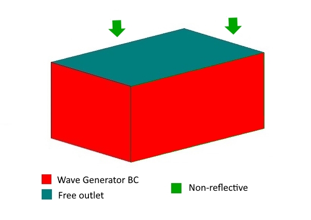
NON-REFLECTING
Usually, the non-reflective BC is applicable for Mach number more than 0.1 and CFL time step equal to 1.
But using non-reflecting BC in shipboard tasks you can also obtain a physical solution for the Mach number < 0.1.
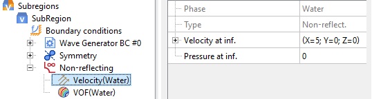
The location of BCs with non-reflective BC for straight directed wave simulation is shown in the figure below:
Oblique WAVES SIMULATION
Oblique waves propagate at some angle to the faces of computational domain (for example, a diagonal wave). To simulate oblique waves, set the Wave Generator BC on the faces determining the wave direction. Set a Free Outlet or a Non-reflecting BC opposite to the Wave Generator BC faces. The location of boundary conditions for oblique waves is shown in the figure below:
MESH
To resolve the free surface, add a mesh thickening to the reference wave line. The simulated wave must be completely located in the thickening area. To increase the solution accuracy, you may use mesh adaptation by condition for the VOF variable . (We will write about this technique in our blog very soon).
 The mesh refinement near the wave baseline
TIME STEP
Specify the following settings for the Time step in the Solver settings:
- Convective CFL = 1
- Surface CFL =1
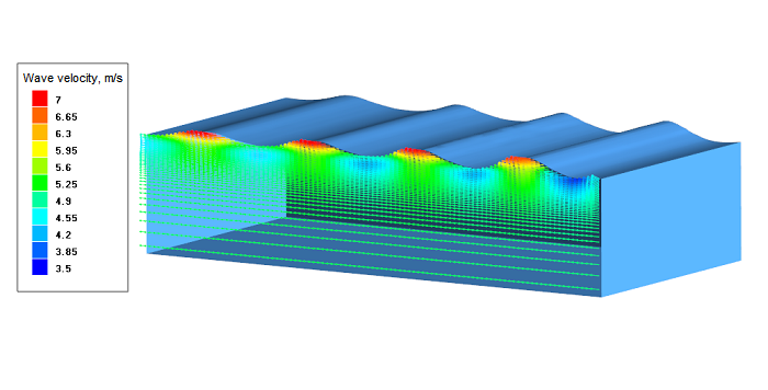
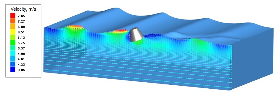
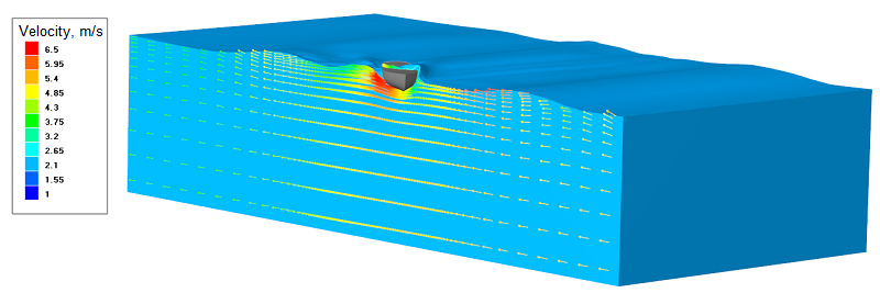
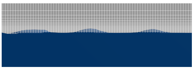
THE RESULTS
FREe SURFACE
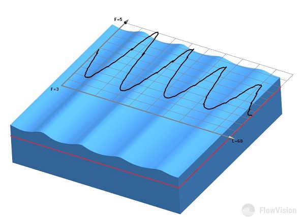
We can see waves in the VOF layer in the PostProcessor!
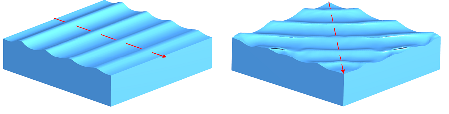
The simulation results for three different types of waves
Wave height
The wave height is determined by integrating the VOF variable on the plane.
To visualize the wave height, create "plot along line" layer in the PostProcessor tab. In the graph properties, select the VOF variable and enable integration of this variable along the normal to the surface. As a result, you can see the minimum and maximum height of the wave, which is counted from the specified level.
where to find the wave generator module
This module is included in the FlowVision 3.12.01 release. (C:\Program Files\FlowVision-3.12.01\SDK\examples)
It`s possible to create your own user modules to simplify work with your common tasks. Contact technical support team support@flowvisioncfd.com for help and advice on users' libraries development.