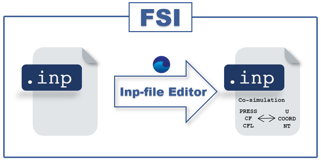
In this article we will talk about our new convenient functionality in FV3.13.01 – an inp-file editor for FlowVision co-simulation with an external finite element software package.
During the FSI-simulation, FV and an external program exchange data through the exchange surface or mapping surface, which can be one of the Surface type objects (ABQ). Remember, that the exchange surface must be closed.
How it worked before FV 3.13.01
Previously, before uploading the created .inp file, it was necessary to modify the .inp file manually, that is, to add the lines responsible for:
- connector type (Direct Coupling or CSE)
- exchange surface name
- send and received FV data via the exchange surface
Starting from FV 3.13.01, there is now no need to add co-simulation lines, since the .inp files are modified automatically for Abaqus CAE and Abaqus Direct Connection/Extended Direct Coupling connectors. Now there is no need to enter the name of the exchange surfaces manually. FV analyzes all the surfaces recorded in the .inp file itself and displays a list of them. User only needs to mark the data by which the programs should exchange.
How it works starting from FV 3.13.01
Let's say we have an .inp file and FV project created and we want to add external connections. We proceed as follows:
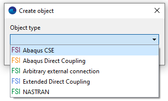
- In the External Connections folder, we create an object with the type Abaqus CSE, Abaqus Direct Coupling and Extended Direct Coupling (the .inp file editor is used only for these connection types. For the rest, loading inp-files are not required).
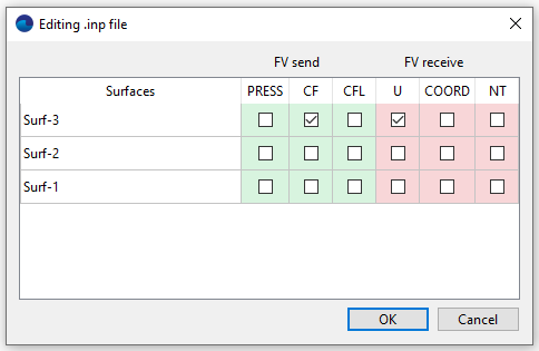
- After selecting the .inp file, the Editing .inp file window appears. The window shows all surfaces (Surface type objects) registered in the .inp file. For the surface on which the pairing will take place, you need to specify data that FV will send and receive.

FV can send:
- PRESS – pressure on element sides
- CF – forces in nodes
- CFL – concentrated heat flux at the node
FV can receive:
- U – displacements (only for the CSE connector)
- COORD – current coordinates
- NT – temperatures
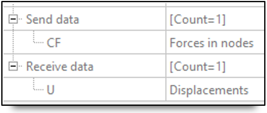
For example, Surf-3 is an exchange surface through which FV sends forces in nodes (CF), and receives displacements (U).
Message about successful .inp file update is displayed after pressing OK button.
The .inp file to be edited must be located in a directory that is allowed for reading and writing.
Based on the modified file, an external connection will be created on the selected exchange surface: Surf-3.
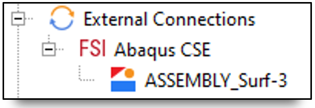
In the properties window of the ASSEMBLY_Surf-3 folder, the data (non-editable) about what FV sends and receives, is specified. In our example, FV sends forces in nodes, and receives displacements.
To conclude
You can create FSI-project in a more quick and convenient way with the built-in editor, which provides user-friendly interface for .inp files editing. Now the preparation of an inp-file takes several seconds, the probability of errors when editing it has become less. A description of errors that may appear during the work with the editor can be found here.
If you have any questions, please contact us at support@flowvisioncfd.com.