In the air conditioning sector, batteries are essential equipment. For this reason, they are included in almost every analysis. In many cases, we need accurate solutions to make changes on our HVAC unit design. CFD analysis can show us internal pressure loses and other air flow characteristics of an HVAC unit. During the design process, we make many changes on the unit design. At this point, CFD analysis provides us an economical solution for testing our preliminary designs before the final design. For this reason, we need to create the correct model for coils in our CFD analysis.
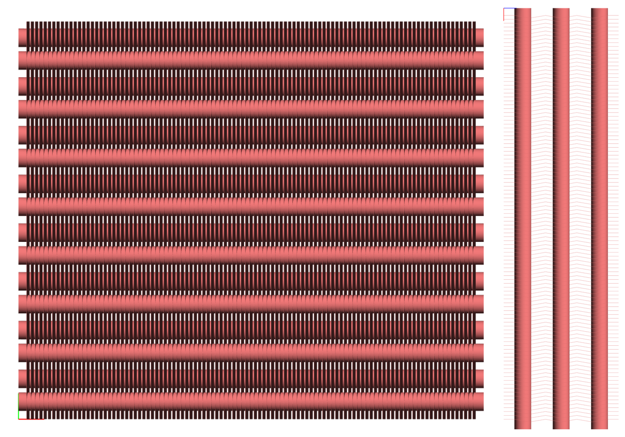
In CFD analysis meshing a coil's real geometry is a very expensive job. You have to create a very dense mesh between coil's lamellas. Creating a dense mesh extends the solution time and consumes too much system resources but it gives more accurate solutions. If you don't have enough system resources then you should try porous medium definition for the coil. For porous medium definition, neither a dense mesh nor a high system resource is necessary. In many cases, porous medium definition works well if you can define the coil's volume resistance correctly in three dimensions. Porous medium solutions are less accurate than real geometry solutions. Here we must make a decision between accuracy and resources. The third option is FlowVision's unique feature named "Gap Model" which provides the real geometry solutions without the need for dense meshing. Current study covers comparison of these three different coil definitions according to their positive and negative aspects.
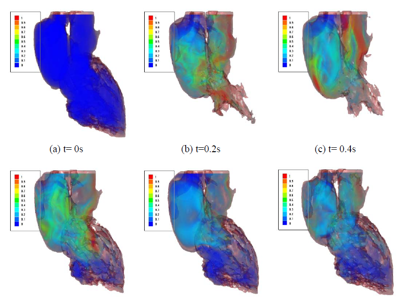
In this paper, the modeling and simulation of the blood flow in the real patient heart is described. In order to cure the patients with cardio vascular disorder it is important to make appropriate choice of an artificial heart valve, it is important to exactly understand the behavior of the heart blood flow of the specific patient under treatment. The presented approach is based on the Magnetic Resonance Imaging/Tomography, which provides the necessary input to create the heart shape (“its geometry”) and its variation in time (tens or hundreds of frames) to define the internal time-dependent heart volumes for one heartbeat. Once this geometry is defined, the CFD software is applied to simulate the internal blood flow and further on visualize it to enable its further analysis. The applied CFD tool is FlowVision, due to its possibility to fully automatically perform the mesh generation of arbitrary shapes, as the heart geometry requires. In addition, FlowVision applies the dynamic mesh refinement by taking into account the motion of the heart-modeled surface, required by the CFD Euler model. The presented CFD approach to simulate the human internal blood flow is validated with data from MRI/MRT scans of the real heart and the respective simulation test cases are presented.
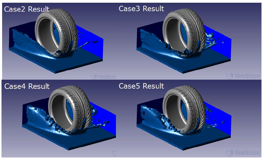
Hydroplaning is a major cause of wet-road accidents. The main contact element between the ground and vehicle is the tire. Tire safety and performance are therefore critically important. Wet roads present several uncontrollable factors. This paper uses CFD (Computational Fluid Dynamics) to analyze wet road hydroplaning effects. Fluid dynamics cannot be easily measured using normal experiments. Therefore the braking distance and record rolling vary by encoder. We propose another method to analysis it. By this result, the large groove and tire depth can reduce hydroplaning effects. A second method is modifying the tire void pattern which can reduce the hydroplaning extent by 29%.
The FDA (U.S. Food & Drug Administration) has partnered with academia and industry the Critical Path Initiative program to create a Guidance Document for industry-wide use proper validation and use of CFD models in the assessment of medical device safety.
CFD simulations are increasingly being used to determine flow patterns and fluid forces in order to evaluate blood-contacting medical devices. It is due to its potential to calculate the values of physical parameters that may affect the level of blood damage the device may cause, such as shear stress or dwell time. Although CFD can decrease the need for expensive prototyping and laboratory testing, there are no standardized and reliable methods available for using CFD techniques in this field.
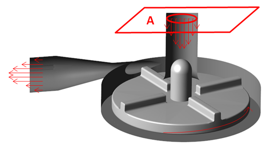
The purpose of this project is to determine the limits of the applicability of CFD techniques by comparing some parameters (such as gauge pressure or shear stresses) of the computational simulations of a blood pump in several working conditions against suitable experimental models. The different conditions included a wide range of velocity profiles at the inlet or different rotor velocities.
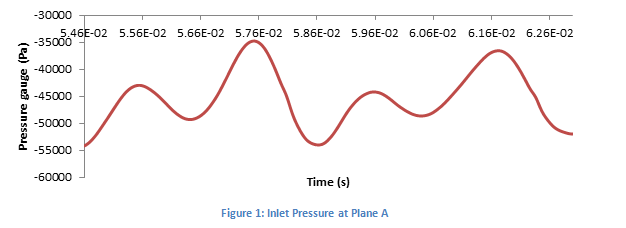
FlowVision moving body capability, together with the real CAD geometry import, has allowed the numerical simulation of this complex case with a relatively simple mesh. Time-dependent results during a whole revolution of the rotor have been obtained, providing consistent and more realistic data for the different scenarios. As example, variables as the pressure gauge behave cyclic with a period of a 1⁄4 of the revolution time, which is consistent with the number of blades.
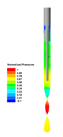
A deeper understanding of the interaction between machine, packaging material and liquid product during the forming process of pouches is enabled by the use of numerical simulation.
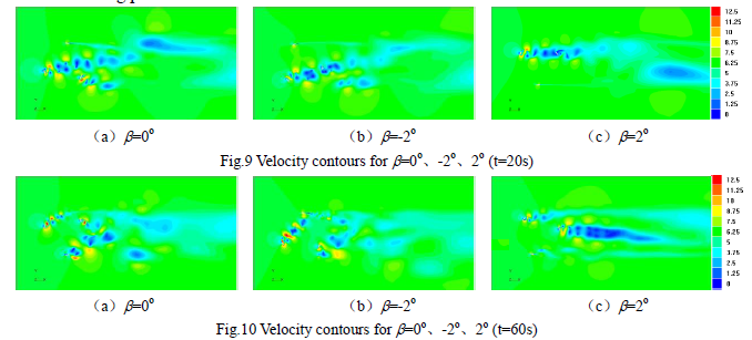
The aerodynamic performance and the bypass flow field of a vertical axis wind turbine under self-starting are investigated using CFD simulations in this paper.
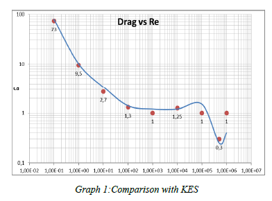
This student work presents CFD analysis of flow over a cylinder for different Reynolds Numbers is explained in this paper by using different turbulence models.
In order to supply tools for low noise design to the manufacturers of lawnmowers CETIM has set up a research project on blade noise (which is predominant on medium size and big machines). Experimental studies are based on the use of a special test rig which allows to measure blade noise without disturbances from the drive unit and to determine simultaneously the pressure fluctuations generated by the blade.
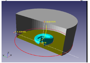
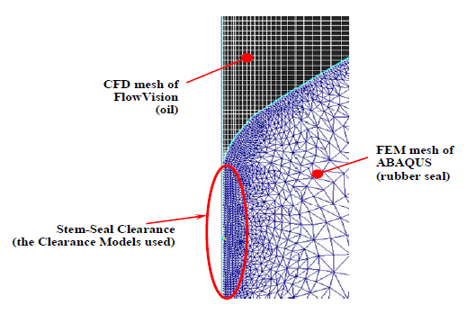
The valve stem seal is an important part of any internal combustion engine. The seal supplies a lubrication of valve stem and limits emission of oil. To design reliable and long-life stem seals a numerical simulation of the seal work is used. Numerical simulation helps to understand the main features of the stem seal working cycle and estimate the changing seal characteristics because of seal aging processes. The problem of oil flow via stem seal involves fluid-structure interaction between an oil flow induced by oscillating stem and deformable seal made from rubber. The Fluid-Structure Interaction Problem is solved numerically by using two codes: Abaqus/Explicit to get deformation of rubber seal and CFD code FlowVision to simulate oil flow.