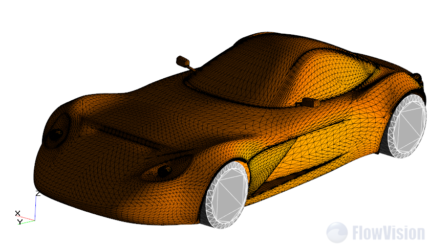
Most prevalent formats of 3D models for FlowVision are STL and VRML. Most of CAD allow to export 3D models to STL and VRML. SolidWorks also allows it.
In this article I will show what parameters of export in SolidWorks will be useful and allow achieving good accuracy of triangulation.
Export to VRML (*.wrl)
FlowVision can work with VRML v1 and v2. But usually other software work only with VRML v1.
WRML allows to contain information about color of surfaces. It is useful, because FlowVision can automatically create separated Boundary conditions which will be based on colors of surfaces. It means that you can create in CAD several different surfaces with different colors and FlowVision will create separated boundary conditions which will be concerned with these surfaces.
Usually (maybe because VRML is standard for demonstration of interactive 3D graphics https://en.wikipedia.org/wiki/VRML ) VRML can be exported from CAD with quality which same as quality of scene which you see in main window of CAD. In SolidWorks quality of triangulation of objects on 3D scene is parameter of VRML export quality.
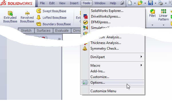
Tools -> Options -> Document properties
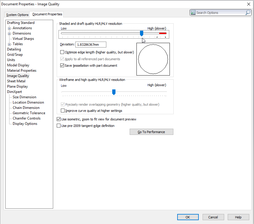
In Document properties tab there are parameters which control quality of visualization of scene. They also determine of quality of triangulation for VRML export. If slider is in red zone you have best quality of triangulation. I suggest to use this red zone for best results during export of VRML.
If 3D scene is too complex, it is possible that export process will very long.
Export to STL
FlowVision do not know about colors in STL. But SolidWorks allows to specify much more high quality of triangulation than it is possible in VRML.
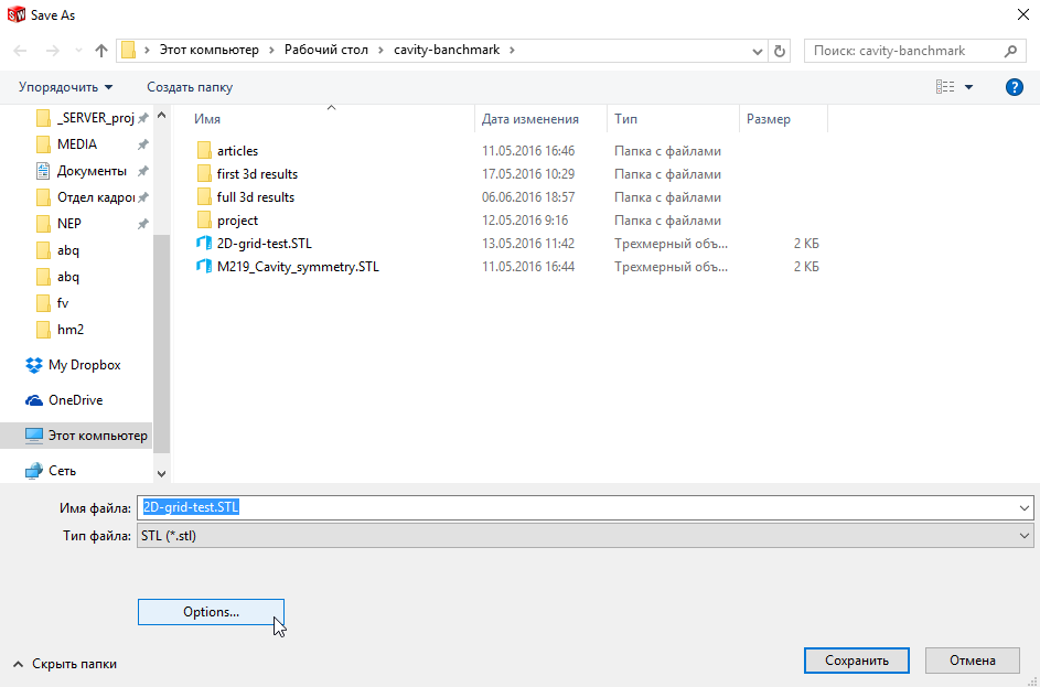
Parameters of export to STL you can find in Export window (Save as dialogue)
File – Save As - STL
In window Export Options there are next parameters:
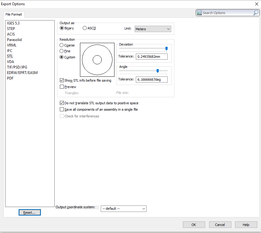
Two sliders allow specifying quality of triangulation.
Deviation usually I use on maximum level.
Angle I use from 10 to 6. I search optimum between count of facets and quality of surface.
Note: Do not translate STL output data to positive space – it is very important checkbox. I suggest to turn on it, in other case Solidworks will lose location of your coordinate system.
Common recommendation which allow to avoid export problems
Unfortunately, algorithms of triangulation in CAD are not perfect. Sometimes result of export is not correct. You can see self-intersections or other problems of triangulation.
In most cases the reason of such problems is too complex shape of surfaces: too small edges and steps or angles between surfaces, connection of two cylinders with very small difference between diameters.
Too small angles is possible to fix by bevel.
Changing of quality of triangulation sometimes allows to fix problems.
There is great software which allow to fix problems of export or allows to translate 3d models from one format to other: 3DTransVidia