There are many improvements in new version of FlowVision 31001. They significantly concern to functionality of adjusting and editing of computational grid such as computational grid adaptation, parameters of boundary layer grid etc. The list of main changes in comparison with FlowVision 31001:
- All adaptations and boundary layer grid are specified now in separate section of project tree named “computational grid”
- In project tree active adaptations and boundary layer grid are highlighted by color while inactive adaptations are grey-colored
- Subregions and geometrical objects in PreProcessor with the same settings of computational grid can be grouped to single subsection of project tree. It is not necessary to repeat this settings separately for each item anymore.
- It is possible to adjust number of layers for intermediate adaptation levels (not only for maximal adaptation level as in previous version). It is not necessary to create such grid during several number of solution steps
- New function is “adaptation by condition” which allow to make split of cells according to specified condition (range of values for variables)
These and other most meaningful features are described below.
New location in project tree
In previous versions settings of computational grid was located in different subsections of section “Subregions”. It was not useful to find settings in different locations:
- Adaptation on Boundary condition (BC) and boundary layer grid in properties of BC
- Adaptation in geometrical objects inside subsection “Adaptation”
- Adaptation to solution in corresponding same-named subsection
In version 31001 all these settings located inside separate section “computational grid” (fig.1)
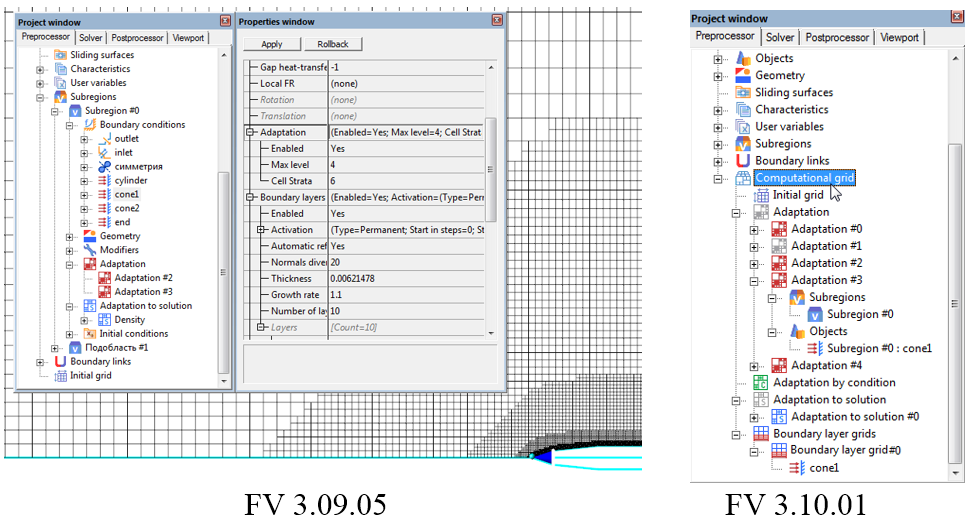
Fig.1.
Highlight of activity in the project tree
For making navigation, more useful, inactive elements of section “Computational grid” are grey, while active elements are colored (fig.1, 31001)
Adjustment of adaptation or boundary layer grid for objects
Adjustment of adaptation now looks differently. To specify adaptation or boundary layer grid you need to do following:
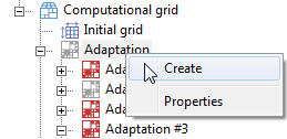
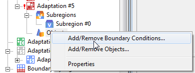
1. Right mouse button (RMB) click on needed element of section “Computational grid” and choose “Create”
2. Then it is necessary to specify subregion where adaptation acts. RMB click on subsection “Subregions” and choose “Add/Remove”.
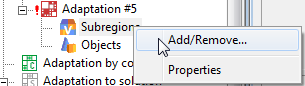
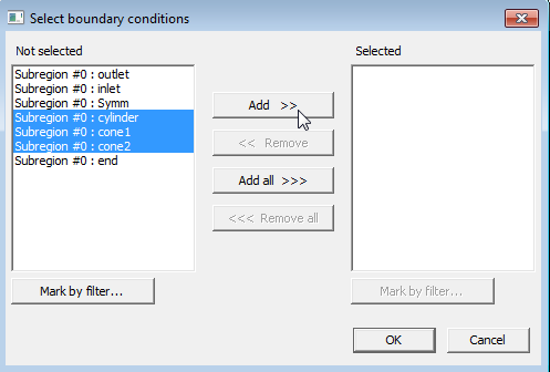
In the appeared window choose the required subregions and click “Add” then press “Ok”.

3. It is necessary to choose Objects for adaptation by the same way in subsection “Objects”. These objects may be geometrical objects existing in preprocessor or BCs. RMB click on “Add/Remove BC” or “Add/Remove Objects”.
4. In the appeared window choose the required BCs or Objects and click “Add” then press “Ok”. You can also mark them by filter, what makes multiselection more useful.
5. Then you need to specify activity settings and other parameters of grid edition in created subsection «Adaptation #..». Finally on this example it was created separate subsection «Adaptation #5» acting for 3 BCs (Fig.2). Note that subsection «Adaptation #..» may include BCs and geometrical Objects same time.
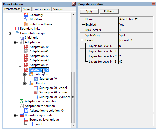
Fig.2
Grouping of Objects with the same settings of adaptation
Fig. 1 shows the example when for three BCs “cone1”, “cone2” and “cylinder” was set the adaptation with the same settings.
It is showed in previous section of this paper, that in new version separate subsection «Adaptation #..» can act on these BCs simultaneously (Fig.2) as well as on set of geometrical objects. It is very useful when there are great number BCs or geometrical objects or subregions, which have the same settings for adaptation.
Simplified management of layers for intermediate adaptation levels
In previous versions for creating of grid with big number of layers for intermediate adaptation levels was necessary to create such grid step by step. It required several number of solution steps and many actions from user. FlowVision 31001 allows you to create such grid making setting at once by specification of number of layers for intermediate adaptation levels (Fig.2). The grid will be generated after single solution step and user can increase number of layers for any adaptation level by adjustment of value for “Layers for Level N ...”. For decreasing of number of layers user have to use adaptation with type “Merge” like in previous versions.
Adaptation to solution
It became a little more ”cleverer”. In particular due to common settings of adaptation on BC with layers of intermediate levels (Fig.2), it do not merge cells of these “layer cake” (Fig.3)
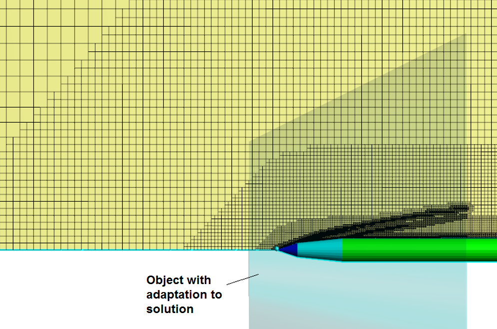
Fig.3
Besides list of available variables for adaptation to solution became wider: now this list include all variables available for post-processing including user variables
Adaptation by condition
This is the new function allowing to make split of cells according to specified condition (range of values for variables). Unlike adaptation to solution with option “to value” adaptation by condition have following features:
- It is not limited by number of created cells
- It have settings for layers for intermediate adaptation levels (it is possible to keep “layer cake” near to adjusted range of variable)
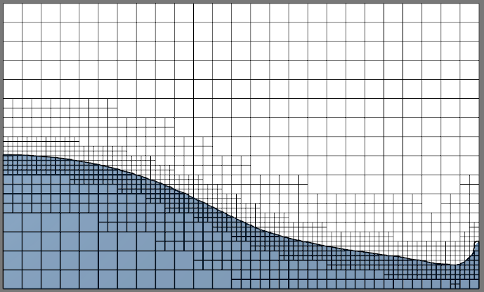
Fig. 4 shows the example with adaptation by condition of variable VOF. It is specified range of variable VOF for which splitting of cells will be performed. In this example it is ensured that free surface always moves inside the grid with the same cell size. Therefore, negative numerical effects minimized because grid is not changes on free surface itself.
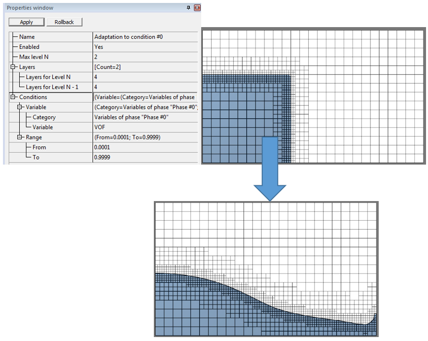
Fig. 4
Note, that for making such “tracking” grid from the beginning of the solution it is necessary perform some actions in addition to settings on Fig.4:
- Because adaptation by condition uses the results of solution on current step, it cannot be applied before end of first time step. Therefore, for first step it is necessary to use regular adaptation on surface of object, where initial condition for fluid (VOF=1) specified.
- For merging of cells far from free surface it is better to use adaptation with type “merge” in volume.
Boundary layer grids
It was marked above that settings of boundary layer grid have changed location from properties of BC into section “computational grid” (Fig.5). Besides, now it is possible to specify boundary layer grid on set of BCs and these BCs will be highlighted when pressing on “Boundary layers of cells #..” in the project tree (Fig.5). However, for present moment it is not allowed to use more than one boundary layer grid (users interface allows it but only one grid will be active). Fig.5 also shows one additional useful feature: number of cells in boundary layer grid (overlapping boundary layer (OBL)) in “status” window .
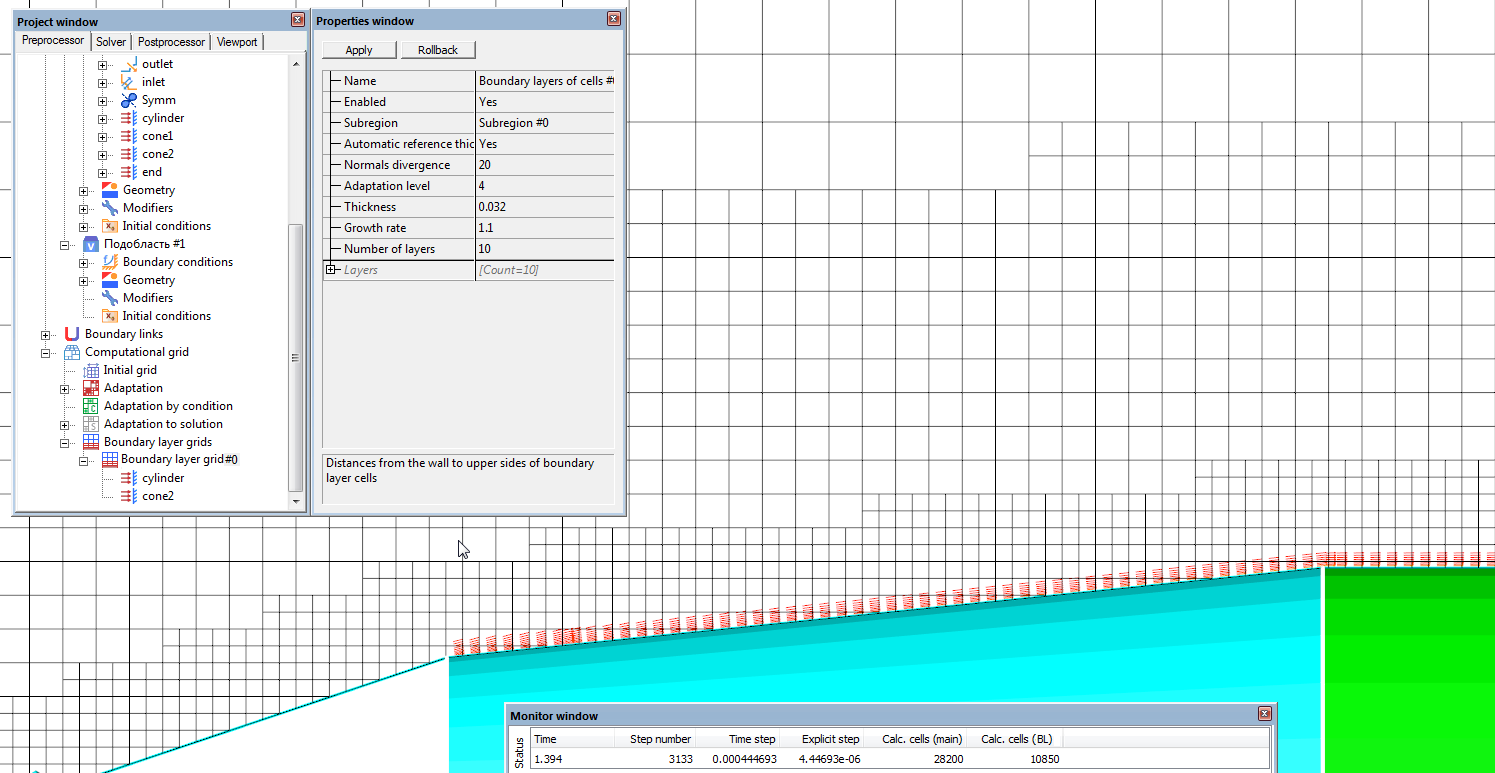
Fig.5
Now it is possible to set maximal “Adaptation level” where boundary layer grid will be created (Fig.5). For example on Fig.5 boundary layer grid will not be created in near-to-wall cells where adaptation level above adjusted value 4. It is useful when user want to resolve part of surface by main grid (e.g. for recirculation zones) and other part by boundary layer grid.
Features of projects conversion from previous versions to 31001
Unfortunately it is not possible to make full conversion of settings from projects created in previous versions. Therefore:
!!! It is strongly recommended to check all settings of computational grid when you opening such project in new version
Better to make settings again, then grid creation will be more optimal and reliable.
However, due to little other order of build creation user should be ready that mesh and number of cells will be slightly different.
The main rules of conversion are following:
- For each object of adaptation (BC or geometrical object) it will be created separate sub-section “Adaptation #..” or “Boundary layers of cells #..” which will contain only single object of adaptation (Fig.6) . In this case for optimization of build creation it is recommended to make grouping of objects with same settings to sub-section “Adaptation #..” which is common for them. For example on Fig.6 user may add to “Objects” of “Adaptation #3” BCs “Cylinder” and “Cone 2” if settings for them the same as for “cone1”. Then user can delete automatically created sub-sections “Adaptation #..” for “Cylinder” and “Cone 2”.

Fig.6.
- Activation of adaptations is converted by difficult and unobvious rule, therefore:
!!!Surely check the settings of activations for all (main and sub-sections) adaptations when opening project in new version 31001
- Head section “Adaptation” in 31001 gets its settings of activation from section “Adaptation” in last subregion of project in previous version (Fig.7, black arrow)
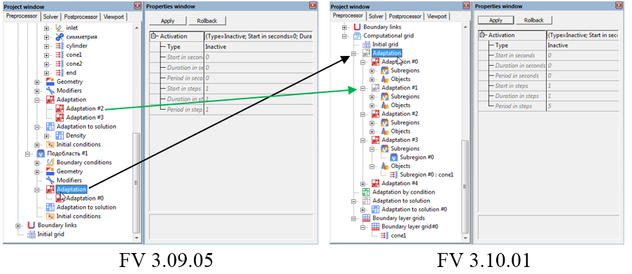
Fig.7.
Individual activation settings of sub-sections “Adaptation #..” in 31001 gets their settings from corresponding sub-sections in projects of previous version (Fig.7, green arrow).