For FlowVision 3.12.01 release we made a breakthrough in the development of processes in dispersed phases. As a result, it became possible to simulate the icing of surface. Today you can apply the both icing modes to your tasks - dry icing mode and wet one. What is the difference between these modes? How to simulate icing processes correctly? What results will be obtained in FlowVision? You will find all answers in this article.
description of natural phenomena
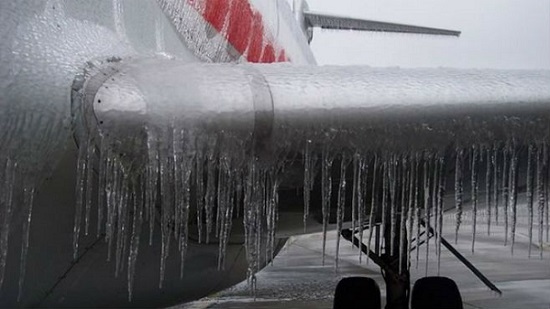
Icing is the process of ice formation on a surface which is streamed by an environment containing drops of water in a supercooled state. During the contact with a cold surface water drops crystallize and form an ice boundary on the surface.
In the troposphere, where the planes fly, the air temperature ranges from 0 ° C to -20 ° C. In addition to an air, there is water vapor, drops of water and ice crystals in the troposphere. Supercooled drops affect the crystallization of water vapor. Therefore, the icing is usual for flying in the clouds or in supercooled rain conditions. Ice formation not only changes the geometry of the wing and therefore increases drag force, but also blocks the moving parts of an aircraft.
There are two types of icing in nature:
- The dry mode. The drops of water reaching the ice surface crystallize instantly.
- The wet mode. The supercooled drops on an ice surface form a film, part of which turns into ice and the another one flows in the direction of the external flow due to the aerodynamic forces.
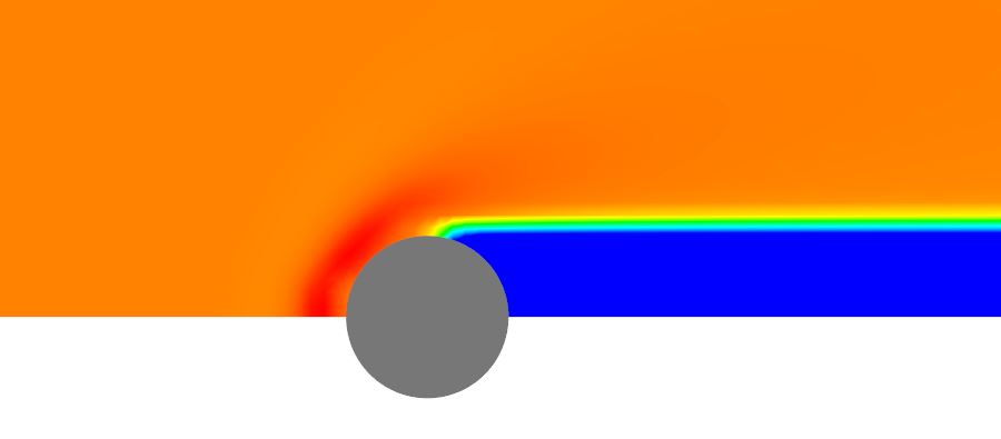
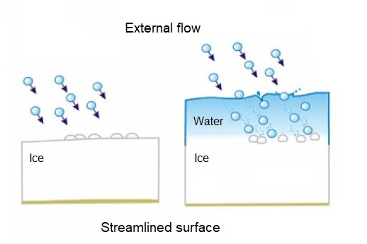 The ice formation for dry (left) and wet (right) icing modes
You may simulate both icing modes using FlowVision. For the dry mode, temperature in contact zone is determined under the ice sublimation. For the wet mode, the flow of a water film over the ice surface can be taken into account. The film freezes due to the evaporation of water and heat transfer to ice and air. As a result of ice accumulation, the geometry of the streamlined object changes, and this affects the flow.
verification
The paper presents the shapes of ice build-ups obtained on the cylinder under different icing modes. Let's check up what FlowVision is capable of. We will try to simulate the same task and compare the results.
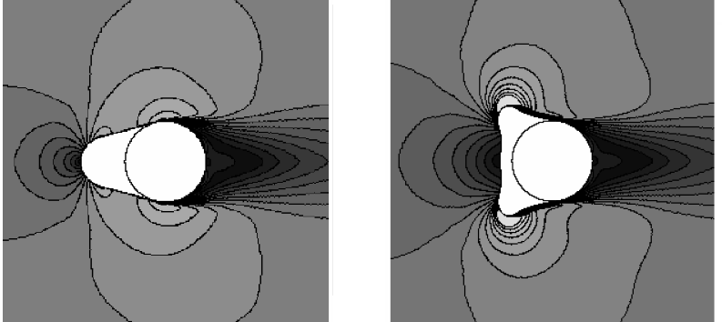 Form of ice build-ups for dry (left) and wet (right) icing modes
modeling in FlowVision
SUBSTANCES AND PHASES
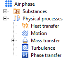
To simulate the icing process in FlowVision, it is necessary to create four substances in PreProcessor: air, water vapor, water and ice. These substances define three phases.
- For the Air phase (air + water vapor of substances) the processes of heat exchange, motion, mixing masstransfer and turbulence can be chosen.
- In the dispersed phase named Droplets, water droplets crystallize due to heat exchange between air and ice phases.
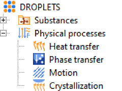
- In the ice phase, the process of accelerated heat transfer is simulated. Due to the difference between time steps for calculation of ice formation and external flow motion, the stabilization of thermal equilibrium in the ice phase will proceed very slowly. To speed up this process, set a large value of the time step coefficient for heat transfer. You may use, for example, 106 value.
Icing simulation ALWAYS STARTS WITH A PRELIMINARY CALCULATION. WHY IS IT so important?
In order to simulate icing process correctly, it is necessary to carry out a preliminary calculation. At this stage, we calculate the external flow without ice formation. Pre-calculation will provide the initial distribution of droplets in the inlet flow. This has a positive effect on the physicality of the process.
At the stage of preliminary calculation, there is no ice formation - it will occur at the next stage of calculation.
Using the preliminary calculation, we provide the ice formation in the place, where it should be in a real physical process. If you do not make a preliminary calculation, then drops begin to crystallize on the surface immediately. As the result, the shape of the icing build-up will be incorrect.
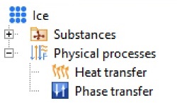
The figure below shows the freestream droplet distribution obtained at the end of the preliminary calculation. The increased concentration of droplets near the surface of the cylinder ensures the correct formation of ice at the further stage of the calculation.
 Volume of the DROPLET phase in the inlet flow at the end of preliminary calculation
Firstly, run a preliminary calculation of the external flow without crystallization (it is usually enough to use about 200-300 steps).
Then start to simulate the formation of ice with enabled crystallization.
Read more about correct pre-calculation in the Icing tutorial.
INITIAL DATA
To start modeling the process, you need to define the initial data:
- Liquid water content (LWC) - the mass of water (moisture) in a unit of volume;
- Outside temperature;
- Droplet size. It depends on the type and height of the clouds.
The icing mode is selected on the base of these data. Dry icing corresponds to Dry model mode, wet icing - to Film model mode.
KEY PARAMETERS
Here we will talk about the key parameters and settings for the numerical simulation of the icing process.
Roughness
Activation of this parameter depends on the used icing mode. It is enabled for film model, but not for dry one.
- For the dry icing mode the surface roughness is not taken into account. The drops from an crystalize on the surface instantly.
- For film mode, roughness affects the result: droplets gradually approach the ice, therefore a rough ice surface is formed.
The roughness is set in the crystallization and turbulence properties of the external flow.
Crystallization
The Shin-Bond roughness mode is implemented in FlowVision. This is an empirical equivalent of the sand roughness.
Turbulence
Typically, for a standard turbulent flow, the roughness constant is about 0.3. But for icing simulation it depends on the Y + value. For the same Y + and similar geometries, the values of the roughness constants should be close.
Film shedding and evaporation
You may activate the film shedding and evaporation models in the crystallization process properties for wet icing to obtain the most realistic physical result.
Time step
The crystallization process is sensitive to the time step. In addition, the processes occurring in different phases require different time step. Let's consider the key time step parameters in icing calculation.
- The surface CFL should be set = 1 in the icing tasks.
- The CFL VOF parameter (from the advanced solver settings) is set to control the formation of the crystalline phase.
We recommend to set CFL VOF = 0.1 ... 0.4 to simulate airplane icing. The lower the CFL VOF value is, the more accurate ice is formed on a surface. But, unfortunately, it decreases the calculation speed. - The Film CFL parameter (from the advanced solver settings) determines the number of calculation cycles occurring within one iteration. This parameter is relevant only for wet icing mode. For dry mode, Film CFL should be equal to any non-negative number. We recommend to set Film CFL = 3 ... 5. With the increase of this parameter the geometry of the ice will be more accurate. Do not forget, that the mesh refinement also affects the solution accuracy.
- The maximum film step (from the advanced solver settings) limits the explicit step for the crystallization process. This allows to avoid the appearance of a large volume of the film at the very beginning of the calculation, then time step usually is very large. We recommend to set maximum film step in the range of 100 ... 600.
Accounting for growth
The ice build-up film on the surfaces changes geometry of object and, as the result, the acting aerodynamic forces. This influence is set by enabling the accounting for growth parameter on the characteristics properties window.
If accounting for growth = NO, the characteristic is calculated only on the surface of the body (BC Wall).
If accounting for growth = YES, the characteristic is calculated over the entire geometry of the streamlined body, including ice build-up.
The results
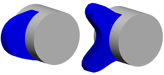
As a result of modeling the modes of dry and wet icing, the forms of ice growths differ from each other and fully correspond to the expected result.
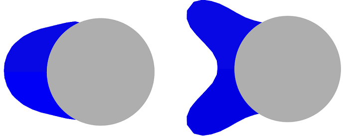
Form of ice build-ups for dry (left) and wet (right) icing modes
conclusion
FlowVision icing functionality has been tested on data from NASA Glenn Icing Research Tunnel (IRT) climatic wind tunnel. Moreover, the calculations are compared with the ones in software products intended for numerical simulation of icing problems: ANSYS FENSAP-ICE, LEWICE.
Helpful Links
- You find more information about icing features in the documentation.
- Look in Icing tutorial. There you will find a detailed step-by-step description how to create an icing project in FlowVision.
- We also have prepared a short Icing Checklist - we hope you find it very useful.